

TeleToyland Sandbox How It Works: Step 7
Step 7: Mount the Servos and Potentiometers, and Calibrate
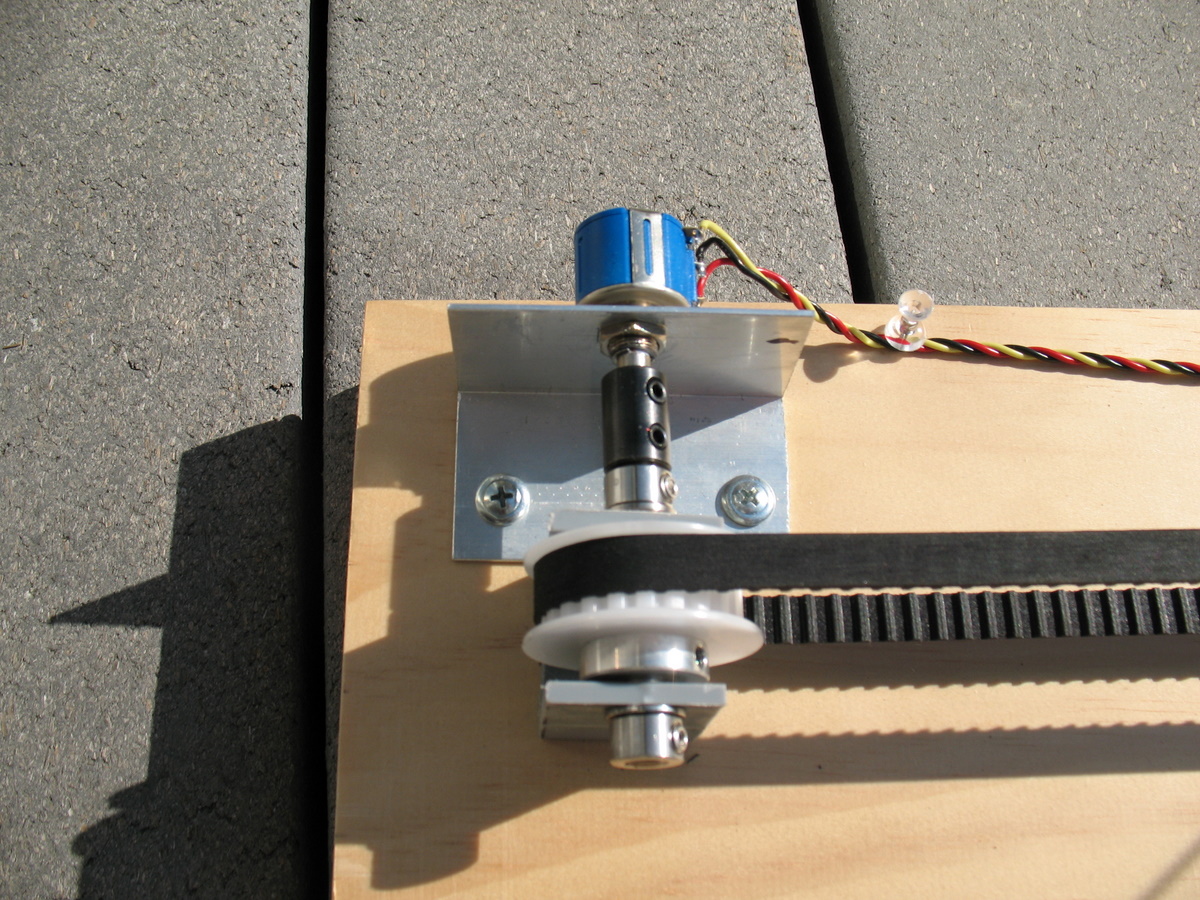
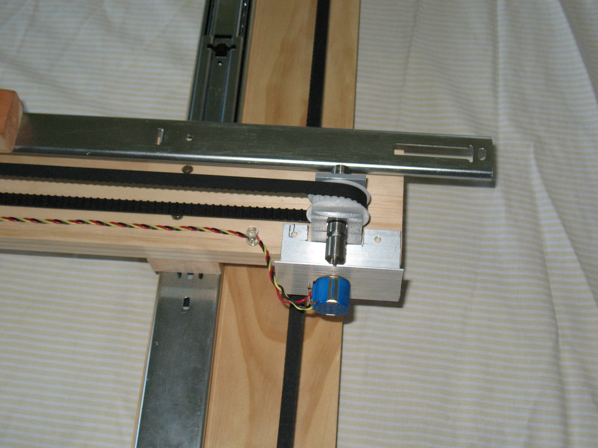
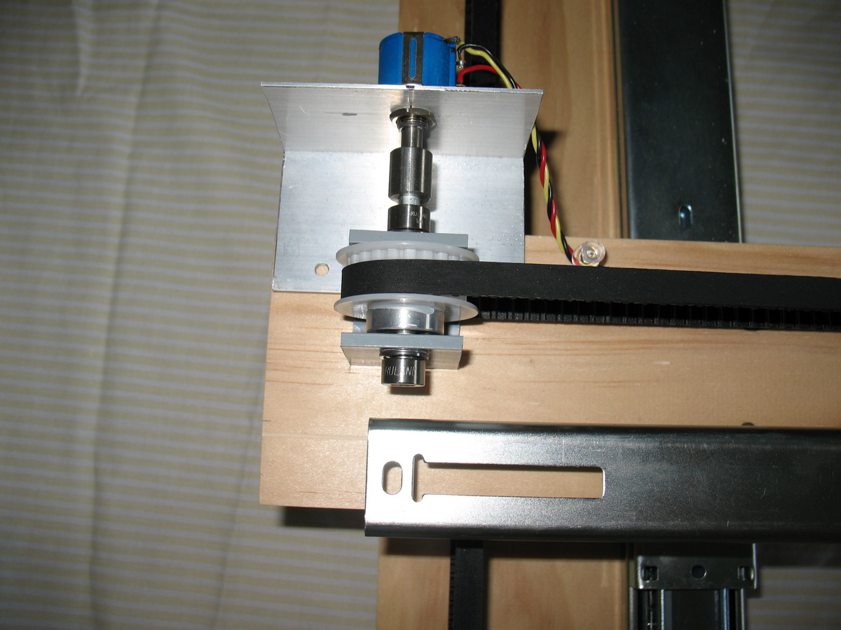
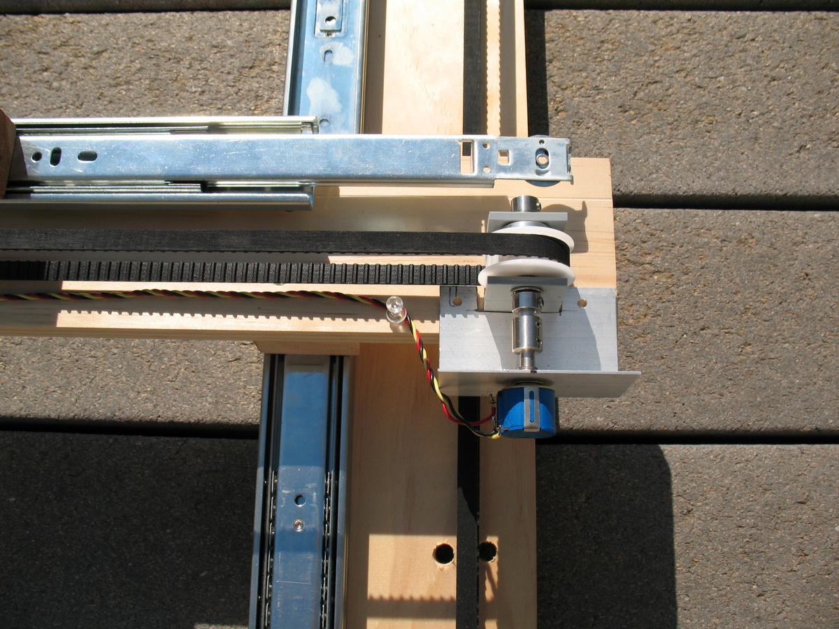
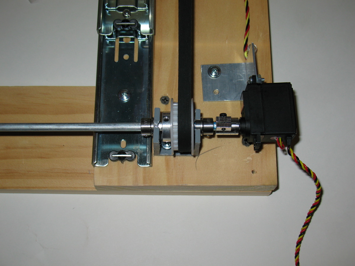
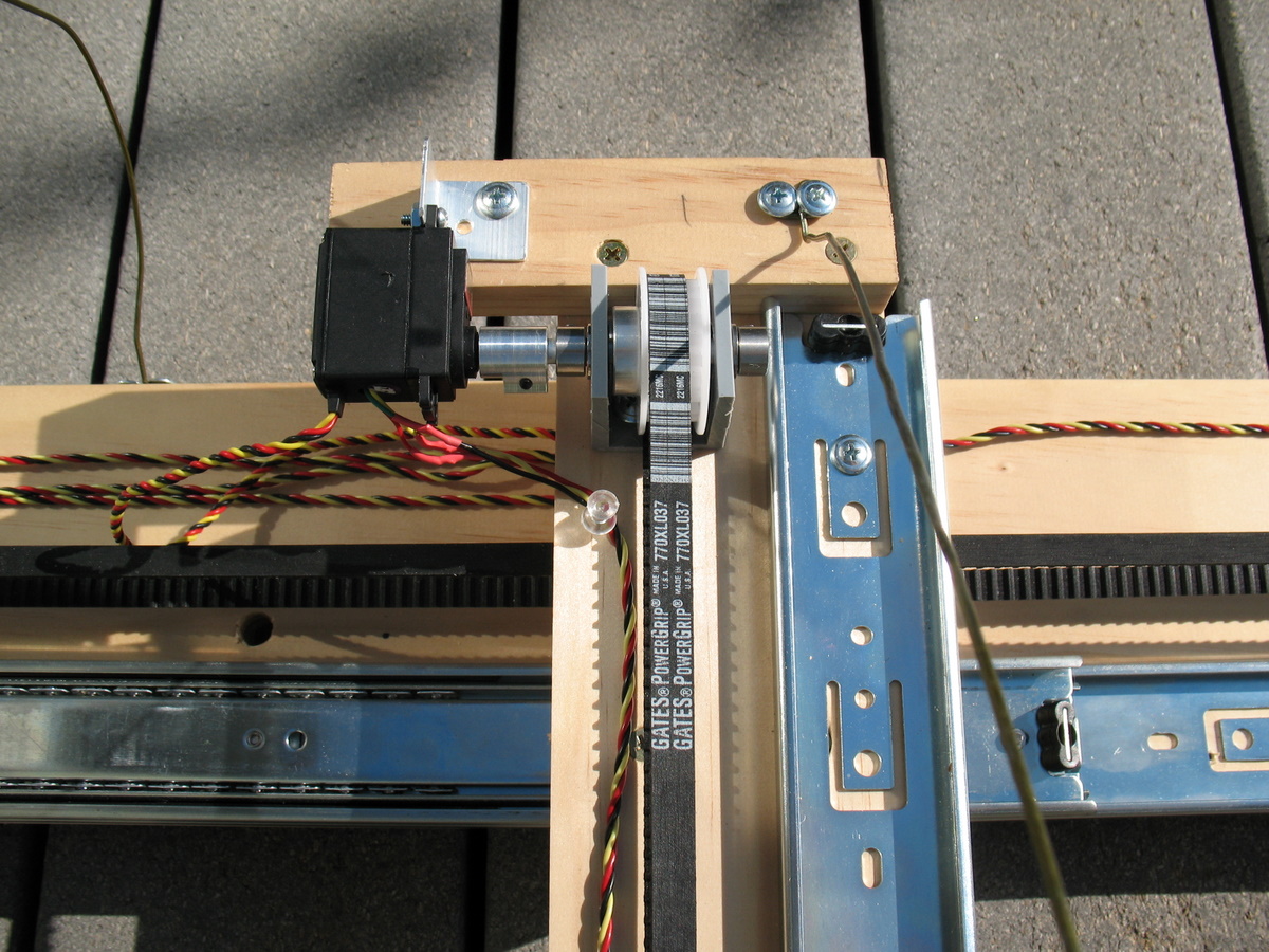
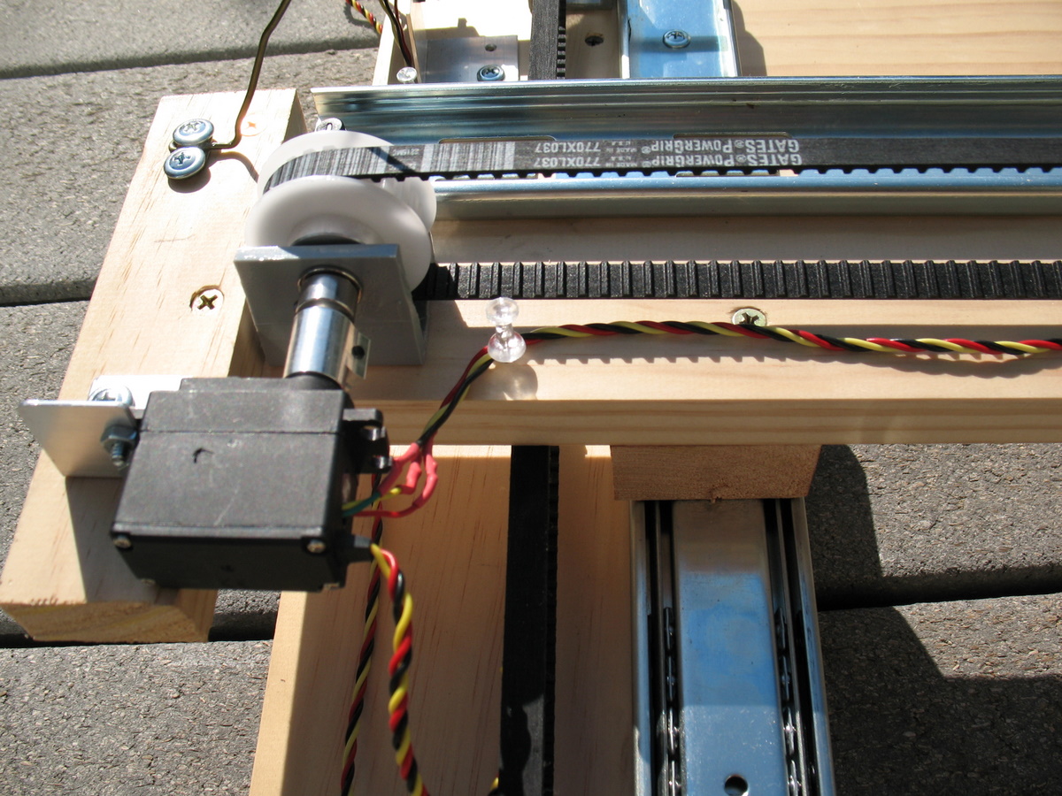
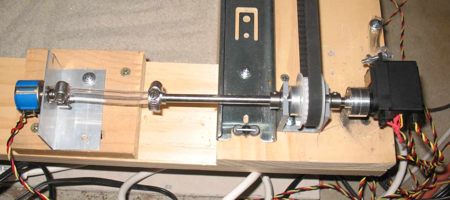
We made L brackets from aluminum to hold the potentiometers and servos in place. At this point, we were just hacking out brackets that fit each situation. They don't need to be very strong - just want to reduce any movement, and they aren't under a lot of pressure. In all cases, using fewer screws and keeping it loose is better since the shaft will not be perfect, and the servos and potentiometer actually move around a bit. We didn't try it (yet), but on some XY tables, we have seen some plastic or rubber hose used to couple the motors to the shaft to allow for movement.Note: we did eventually have issues with the potentiometers, and have replaced them with longer-life hybrid ones and also have now used (2-3" pieces of) plastic tubing to mount them to the shaft. In addition, we moved the shaft that connects the two sides to the other side, and now have the X axis potentiometer sharing a short shaft with the X axis servo. (see last picture)
Leave the potentiometer and servo couplers loose, move the stage to approximately the center of travel and drive the servos to the center position (using a servo tester, an R/C transmitter or serial servo control board like the Lynxmotion SSC-32). Then turn the potentiometer until the servo stops, looking for the point where the servo slows down and switches direction. Once you find that point, then lock the set screws down. Note that servo testers and R/C radios may go 90 degrees, while SSCs usually can drive servos to 180 degrees. This is important to get the full range of motion - will use more of the potentiometer range.
We didn't worry too much about having it exactly in the middle since we are driving them by computer and needed to set the servo commands for the min and max position anyway.
Intro | 1 | 2 | 3 | 4 | 5 | 6 | 7 | 8